Structural Engineering Basics for Beginners (1 of 2): Statics Summarized
Structural engineering is one of the major branches of civil engineering and probably the first that comes to mind when we talk about Civil Engineering. It is studied in Civil Engineering by first learning Statics, and then Strength of Materials subjects. So in this first part of structural engineering basics posts, we will summarize statics, and in the next one, building on the knowledge gained here, we will summarize strength of materials subjects. For civil engineering students, or anyone else who is not an engineer, these two posts should be useful summaries to look at. We wanted to make these two posts, because whenever we talk about structural engineering and sometimes even geotechnical engineering related subjects on this website, even though we always pay attention to make our posts as plain language as possible, we want our visitors who are not engineers to be able to follow us better, so we will refer them to here.
So now let’s begin with our summary of Statics, the most fundamental class of all, in Civil Engineering…
In structural engineering everything stems from the laws of nature that were explained by the great scientist Sir Isaac Newton more than three centuries ago (Principia, 1687).
According to Newton’s first law, an object will remain at rest, or will keep moving in a straight line with steady speed, unless a force acts on it.
Newton’s second law, F=ma, states that when there is a net force acting on an object, it accelerates or decelerates, and this depends on its mass. This law is used in structural dynamics and earthquake engineering, but not in statics. We mention this in earthquake engineering related posts in ConstructMagazine.Com.
And according to Newton’s third law, when an object exerts force on another object, the second one will exert force on the first with equal magnitude but opposite in direction.
The 1st and 3rd laws of Newton, establish the starting point of statics.
So using the 1st law, if the object is at rest, then it means the net force acting on the object is 0. For example, if we have a glass on a table, and it is at rest, the weight force of the glass is countered by the supporting force from the table, equal and opposite in direction. This balance is equilibrium, not the 3rd law. The 3rd law pair of the table pushing up on the glass is the glass pushing down on the table. So we can also say that the table is at rest because the force from the glass, plus the weight of table, is equally countered by the supporting reactions from the floor.
We can draw this state of the forces acting on the table, by something which we call “Free Body Diagram” where all these forces are shown on the object which is at rest. More generally FBD is a diagram of an isolated body showing the external forces and moments acting on it (so it is actually also used on a moving object, as in dynamics too).
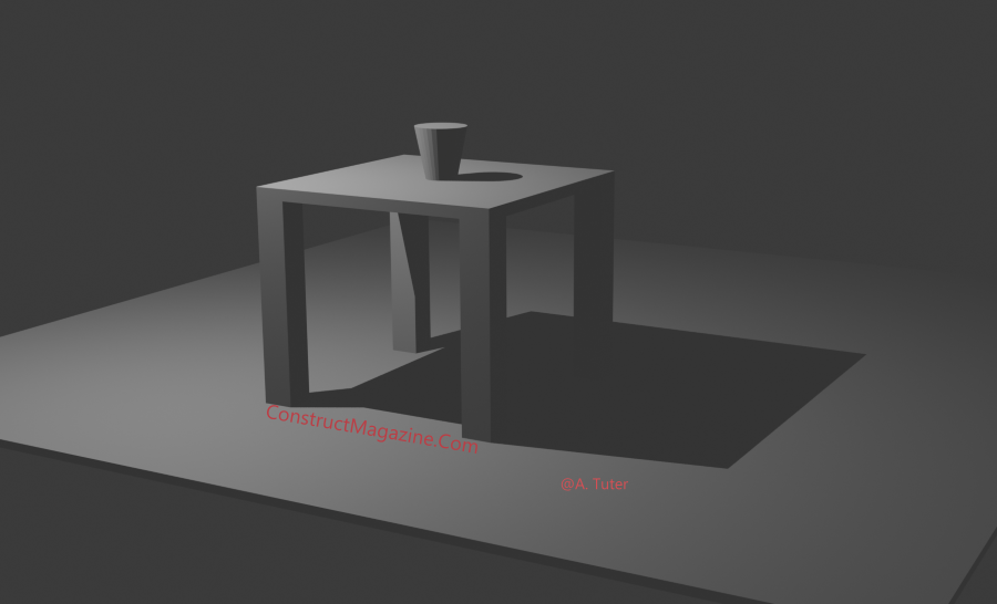
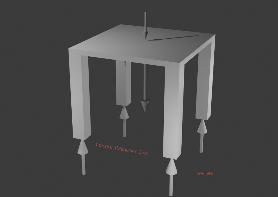
Since the net force on the object is zero, we can also say that the sum of forces in all x, y and z directions are zero (in 3D, we take x and y on the paper plane we look at, and z as perpendicular to it):
Σ Fx = 0
Σ Fy = 0
Σ Fz = 0
These are called equations of equilibrium and they are the most fundamental equations in civil engineering. All structures we build must satisfy these equations otherwise it means they will move and consequently may fail. In addition, objects may not only move but they may also rotate. So to these, we will also add three equilibrium equations for rotations, which we call “moment” as we will see below.
All forces are vectors. A vector is something that has direction and magnitude. For example temperature is not a vector because it only has magnitude, not direction. But a force is a vector because it has both magnitude and direction. We show a vector with an arrow, which is drawn in the vector’s direction and with a length in proportion to the vector’s magnitude. So in the figure above the weight of the glass, which is shown by a small downwards arrow, and the weight of the table, which is shown by a much larger downwards arrow, represent their weights. And the four arrows at the legs, represent the reaction forces from the ground. Since we must satisfy the equations of equilibrium we wrote above, all these arrows must sum up to zero. In this case they are all vertical, which is represented by y axis. Note that we already do not have horizontal forces here so x and z are already zero. So when we add the forces in y axis together, if the weight of glass is, say, 4 N, and the weight of the table is, say, 96N, then we have 100 N downwards force. These are countered by the four reaction forces from the floor. Since they are distributed symmetrically, we can immediately say (without having to solve) that, each of these reaction forces are 100/4= 25 N. Here if we accept downwards forces as minus, we must then accept upwards forces as plus, since they are in opposite direction and direction matters in vectors. Vectors can be added, subtracted or even multiplied. A force can be moved anywhere along its line of action without changing its external effect on a rigid body, such as the support reactions it causes. This is called the principle of transmissibility. Its internal effects, however, do change: moving a force changes which parts of the member are stressed and how it deforms. Force deformation relationships are covered in the next post, strength of materials.
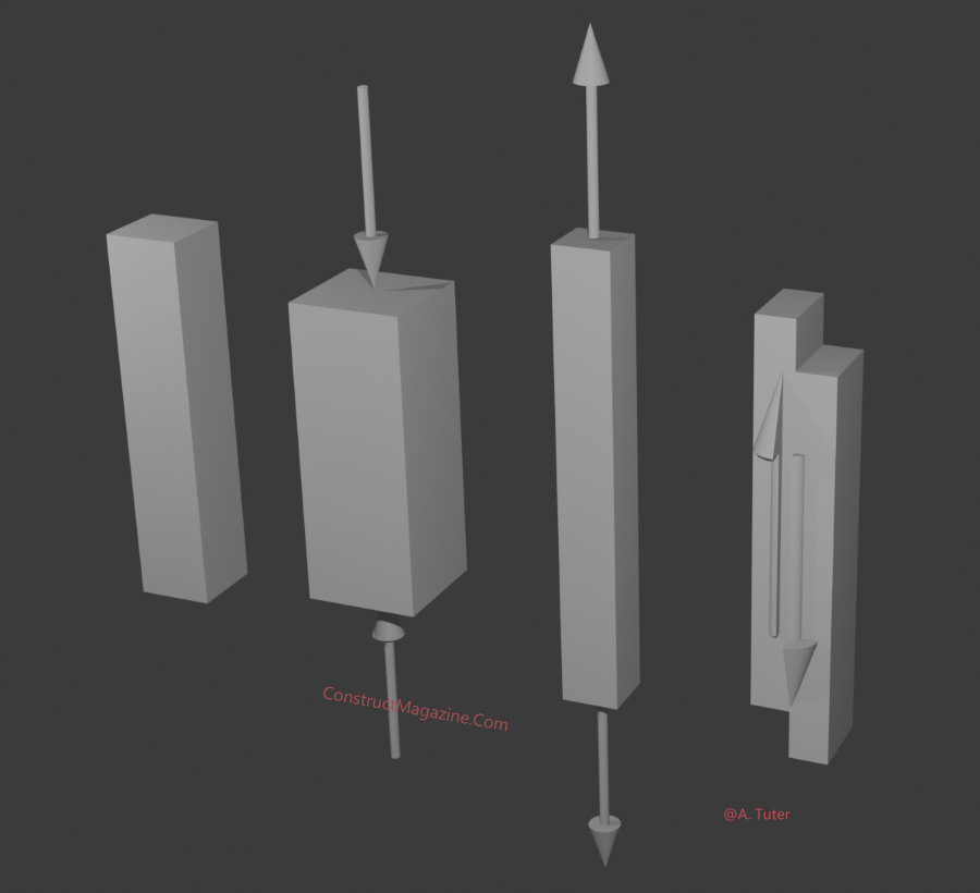
All forces are vectors, but we can still classify them in civil engineering according to how they act on bodies. For example a force may try to compress an object by pushing it, or it may try to expand / lengthen an object by pulling it, or it may act as if trying to cut that object. The first is called compressive, second one is called tensile, and third is called shear force as seen in the figure below. Note that we first showed an undeformed element, and then exaggerated how the forces deform it, to clearly demonstrate the subject only. Otherwise, deformations in civil engineering are rarely detectable with the naked eye.
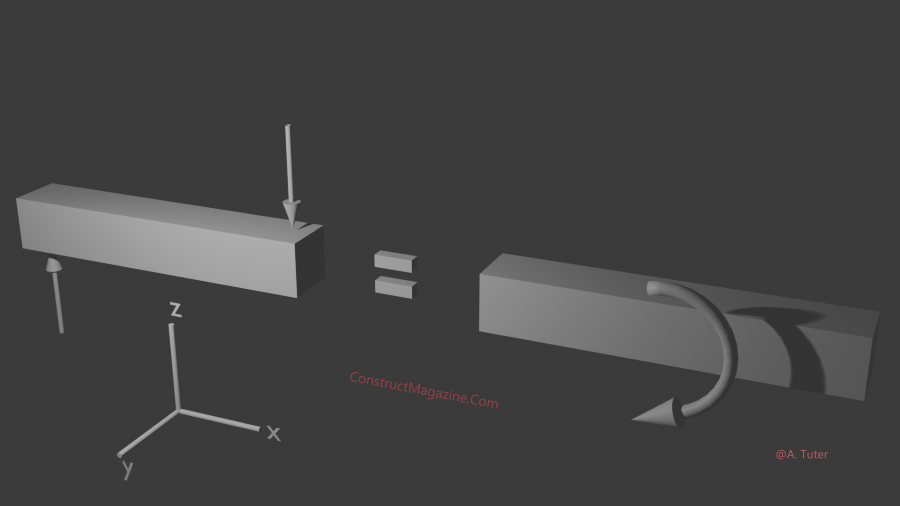
There is also the “moment”, which is the turning effect of the force. It is obtained by multiplying the force by perpendicular distance of force to the rotating point, such as M=F.d. For example, the moment on the beam below is obtained by multiplying magnitude of one of the forces below by the distance between them. And on the right, you see how we show this moment. So statically at least, the beams on the left and right below are totally equal to each other. And we call the forces on the left, Fy1 and Fy2 along y axis a “force couple”. The forces in a couple cancel each other, except that they have distance between them, and therefore create moment, and only the moment remains, just like in the figure below. This moment rotates around z axis, so we call it Mz.
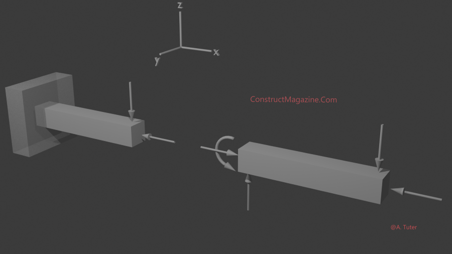
So for example, in the figure below, see the beam, which is fixed to the wall at Point A. If we apply the two forces along x and y axes, as shown at the tip of the beam at Point B, then we can draw the FBD – Free Body Diagram of the beam, as shown on the right. See how the wall produced the reactions at point A. The beam below is at rest, therefore it is in equilibrium. For example, in x axis, we have the external force on the right, and equal and opposite reaction on the left which makes Σ Fx = 0. For z axis, we already have no force, therefore, Σ Fz = 0. And for y axis, the vertical downward external force is countered by the upward reaction of equal magnitude on the left side so Σ Fy = 0. Therefore we satisfy equilibrium equations for forces. And there is also moment created in the wall. This is because there is distance between the vertical forces which creates moment, which must be resisted by the moment reaction at the wall. This makes Σ Mz = 0. We say Mz because it is the rotation around z axis.
In the figure above we also saw that we should add moment equilibrium equations to the force equilibrium equations we had written earlier. So the complete set of equilibrium equations becomes:
Σ Fx = 0
Σ Fy = 0
Σ Fz = 0
Σ Mx = 0
Σ My = 0
Σ Mz = 0
These six equations must be satisfied for every object in 3D, in order for it to be at rest (equilibrium). Above, Mx means, the moment that rotates around x axis and so on. For simplicity, we often solve problems in 2D in statics. In such cases, for a 2D problem, we will only have as we showed before
Σ Fx = 0
Σ Fy = 0
Σ Mz = 0 (pay attention, this is moment, which rotates around z axis perpendicular to paper)
So when we solve a 2D problem on paper plane, x will be horizontal, y will be vertical (as was the case in 3D), and z will be the dimension out of plane, around which the moments created by forces on xy plane will occur.
In the figure above, where the beam was fixed to the wall, the wall was able to create all required reactions. This is called a fixed support, when one member is simply fixed into another member. Fixed support is the most widely used support type in structural engineering. But there are surely other cases where a fixed support will not work for us. For example, for a structural reason, we may want to release moment there, in other words, we may want moment to be zero. In such case we must use a hinge support. If, in the figure above we had a hinge between the beam and the wall, the hinge would be able to resist vertical and horizontal forces, but, it would not be able to resist the moment created by the vertical force couple in vertical direction. This means, our beam would rotate. This is called a mechanism and it is not acceptable in structural engineering. It means failure. So, if we had a hinge between the beam and the wall, to prevent a mechanism formation, we would need to restrain the rotation of the beam in another way, such as having it bear on a surface at its right end or somewhere in the middle at least.
To this point, we have learned the most fundamental concepts in statics. There are two more essential things to learn in statics, and they are very important, in fact, they are the goal of what we studied above, but they are all based on what you have seen so far.
The first one is, by using the principles given above, when we are given a problem with some structural members on which external forces act, we are able to find the support reactions. For a 2D problem, we use the three equilibrium equations given above, to find these reactions. This means, we can have 3 unknown reactions, to be able to solve it, since we have 3 equations available. This is called a determinate structure (provided the reactions are not all parallel or all meeting at one point; with fewer reactions, the structure is unstable). In cases where we have more unknown reactions than the equilibrium equations, which is usually the case in real life – and it is good because it means redundancy – then it is an indeterminate structure. Solving indeterminate structure is out of scope of statics, and is studied in structural analysis class later. In the YouTube link and the reference book link below, the subjects in this post are explained in greater detail, and also some additional concepts and knowledge based on what we learned here are covered such as more detail on vectors, loading, types of supports, trusses, example to find support reactions, a more detailed example and additional points about force and moment diagrams (see below). You can also find a ton of info on the web for all of these, now that you know what to look for.
And the second one is, after finding the support reactions, we are also able to determine which forces and moment do we have at what location of the member or member internally, which are graphically shown on what we call as “force and moment diagrams”. This is very important to know for us, to design members, and really the ultimate thing we want to reach in any structural analysis problem.
For example, for our beam shown above, which was fixed to the wall at Point A, if we wanted to show Fx, Fy and Mz diagrams along the beam, which shows us their values at any point within the beam internally, we would draw the diagram as below:
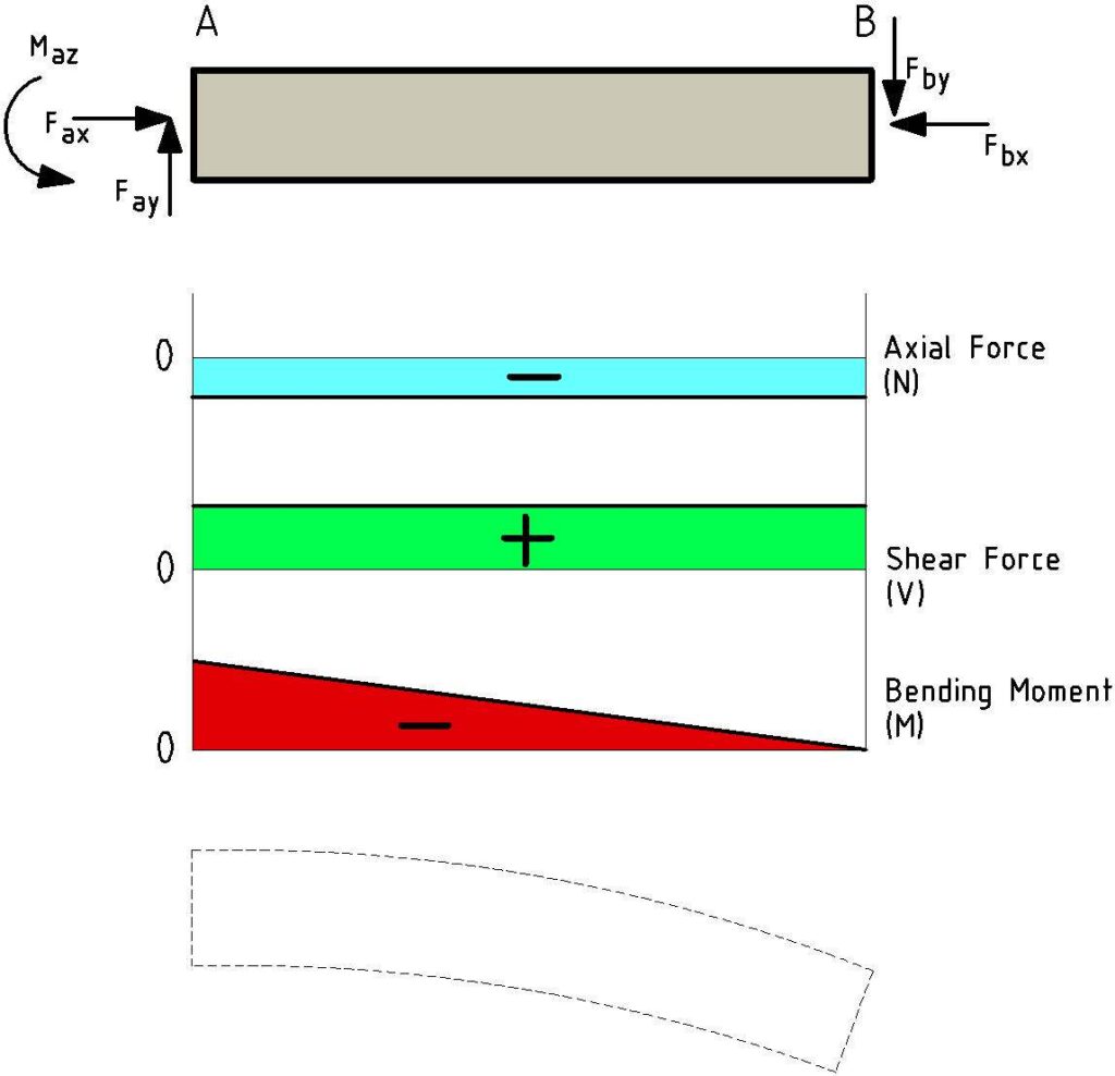
In the graph above, Fx is the Axial (normal) force, along the beam direction. As you can see, we have two forces Fax and Fbx equal in magnitude, pushing from both ends of the beam, which puts it in compression. So we have a constant axial force. Look at the blue area, which shows this. We showed it as negative, because we take compression as negative, as our sign convention in statics. If the beam was in tension, we would show axial force as positive for example.
Then we have the Shear force, which is the vertical force acting on the beam cross section. Look at the green area, which shows this. At point A we have this upwards reaction, and at point B we have this downwards force. They are equal in magnitude, per Newton’s law. So now assume, we start at point A, and move a little bit to the right and cut the beam there vertically. We would have an internal force equal in magnitude to the force at point A but opposite direction. If we keep doing this until point B, all we get is those constant internal shear force values. Therefore, we have again a constant value, and this time we give it a positive sign, again per our sign convention in statics (this is explained in the reference links below).
And finally we have Moment, the rotation effect of force. See how our wall was able to resist the turning effect and produced a reaction moment at point A. Look at the red area, which shows this. This moment value is shown with a negative sign at the wall, again per our sign convention, and then gradually decreases and at point B, the right end of the beam, it becomes zero, which is only logical because the free end of the beam has no external moment applied, nor any moment can be resisted there. You may wonder why we drew moment above zero line although we say it is negative. This is the convention. This also resembles the bent shape of the beam (or rather, the sign of the moment corresponds to the direction of curvature), because concave down bending as in here, means negative moment by sign convention. The bottom figure shows the deflected shape. Pay attention, how the bottom of this beam is in compression and top side is in tension, to which we will take a closer look in the next post, strength of materials.
Overall, this is really about it, for statics subject, at least if one wanted to summarize its fundamental concepts. This was the first of our two posts that introduces fundamentals of structural engineering. The next post covers strength of materials, which builds on the information given here and introduces other very important and new fundamental concepts. These two subjects, statics and strength of materials, are also studied in an undergraduate degree in this order.
Reference from author’s book: https://www.amazon.com/dp/1943605068
Also see our video on Youtube on this subject: https://www.youtube.com/watch?v=o5hVqpooDm8
Post By: A. Tuter
Terms of Use: Unauthorized copying is prohibited; we maintain dated records to document original publication. Content may contain inaccuracies. See our Terms Page.