Common Earthquake Failure Modes in Steel-Frame Buildings
Steel-frame buildings can provide excellent seismic performance when properly designed and detailed. However, earthquakes subject steel members and connections to repeated cycles of tension, compression, bending, and shear. Inadequate design, detailing, fabrication, or construction can lead to several steel-specific failure modes.
General Steel-Frame Failures
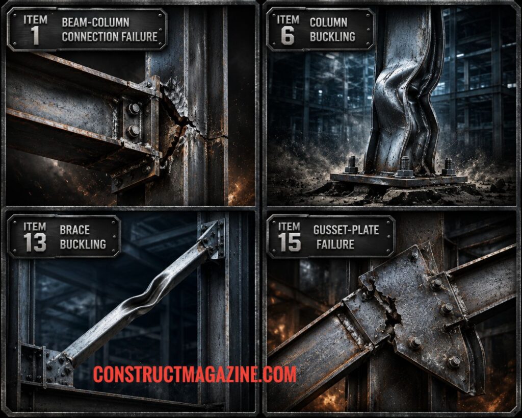
1. Beam-Column Connection Failure
Beam-column connections in moment-resisting frames experience large cyclic bending moments and shear forces.
Modern seismic connections are specifically detailed and tested to develop ductile behavior, but inadequate or older detailing can result in excessive deformation, weld fracture, bolt failure, or other brittle connection failures. Weld defects such as lack of fusion or incomplete penetration can further increase fracture risk.
For example, in older welded moment connections, brittle fracture could initiate at the beam-flange-to-column-flange weld or near the weld access hole under repeated seismic cycles. Modern prequalified connections use controlled connection geometry, appropriate weld and bolt detailing, protected yielding regions, and qualification testing to ensure that plastic rotation develops in the intended location without premature brittle fracture of the connection.
2. Panel-Zone Failure
The panel zone is the portion of the column web between the beam flanges within a beam-column joint. During an earthquake, beam moments create high shear forces in the column web, which can cause excessive shear yielding and distortion.
Controlled panel-zone yielding may be part of the intended ductile mechanism, but excessive deformation or web buckling can compromise the joint. High column axial forces can further increase these demands.
The panel zone must therefore be designed so that its behavior is compatible with the intended beam-column connection mechanism.
3. Beam Plastic-Hinge Degradation
In ductile moment-resisting frames, plastic hinges are intentionally formed in beams at predetermined locations to dissipate seismic energy. The concern is premature degradation or loss of plastic rotation capacity caused by excessive cyclic deterioration, local instability, or fracture.
4. Local Buckling of Steel Members
Local buckling occurs when a relatively thin flange or web becomes unstable under compression or shear. It can reduce strength and stiffness and limit plastic rotation capacity.
Local buckling and plastic-hinge behavior are distinct: local buckling may occur within a plastic-hinge region, but controlled plastic hinging itself is not a failure.
5. Lateral-Torsional Buckling of Beams
The compression flange of a beam can buckle laterally when it is insufficiently restrained, causing the beam to move laterally and twist. Local flange buckling and lateral-torsional buckling can also interact.
6. Column Buckling
Columns experience combined axial force and lateral deflection during earthquakes. As a result, they may undergo global buckling or local buckling of their flanges or webs. Global buckling is particularly serious because a severely buckled column can lose its load-carrying capacity and potentially trigger overall structural collapse..
7. Brittle Fracture and Low-Cycle Fatigue
Steel members and connections can experience fracture after repeated inelastic cycles. Weld metal and heat-affected zones (HAZ) are particularly vulnerable to low-cycle fatigue cracking. Stress concentrations, weld defects, inadequate toughness, and poor detailing can accelerate fracture. Unlike ductile yielding, brittle fracture can occur suddenly with little deformation.
8. Shear Failure of Steel Members and Connections
Steel webs, bolts, welds, and connection components can experience high seismic shear forces. Failure may occur through web yielding or buckling, bolt shear, or weld failure. Undesirable brittle shear failure should be prevented before intended ductile mechanisms develop.
9. Net-Section Fracture
Tension members and connections can fracture through their reduced net section, particularly at bolt holes or other stress concentrations. Under cyclic loading, repeated inelastic strain can accelerate fatigue and eventual fracture.
10. Block Shear Rupture
Block shear rupture can occur in bolted tension connections, including brace, gusset-plate, and splice connections. A block of steel tears along a combined path of tension and shear around the connection. It is a valid connection limit state, although generally less prominent in earthquake damage than other fracture mechanisms.
11. Column-Splice Failure
Column splices may experience high axial forces, bending moments, and shear during earthquakes. Failure can involve bolt fracture or slip, weld failure, plate yielding, or local instability. Modern seismic provisions impose stringent requirements on column-splice strength and ductility, particularly in high-demand moment frames.
12. Column-Base, Base-Plate, and Anchor-Bolt Failure
Seismic overturning forces can produce significant forces at the column base.
Failures may include anchor-bolt fracture, excessive base-plate deformation, concrete breakout, or inadequate shear and overturning resistance. Insufficient rotational capacity or unexpected flexibility at the base can also alter the intended moment distribution and plastic-hinge locations.
Braced-Frame Failures
13. Brace Buckling
In concentrically braced frames, braces experience alternating tension and compression. Compression braces may buckle, substantially reducing their stiffness and affecting subsequent seismic cycles.
14. Brace Fracture
Repeated tension yielding and compression buckling can cause braces to accumulate low-cycle fatigue damage. When a brace buckles out of plane, severe cyclic bending can develop around the buckled region, accelerating fatigue damage and potentially leading to fracture.
15. Gusset-Plate Failure
Gusset plates connecting braces to beams or columns can experience yielding, buckling, tearing, or fracture under large seismic forces. Their connections can also fail.
Specialized Seismic-System Failures
16. EBF Link Failure
In eccentrically braced frames (EBFs), the link beam is intentionally designed to dissipate seismic energy through controlled inelastic action. Excessive shear yielding, local web buckling, low-cycle fatigue, tearing, or stiffener-weld fracture can cause premature loss of link strength and energy-dissipation capacity.
17. Buckling-Restrained Brace Failure
Buckling-restrained braces (BRBs) are designed to prevent global brace buckling, but their yielding cores and transition regions have their own failure modes. Excessive cyclic strain can cause low-cycle fatigue fracture of the steel core, while local instability can develop in unrestrained transition regions.
18. Collector and Diaphragm Load-Path Failure
Collectors (drag struts) gather seismic forces from the floor diaphragm and transfer them to the vertical lateral-force-resisting elements. The diaphragm must transfer in-plane seismic shear through the floor deck and its connections.
In steel-framed buildings with steel deck diaphragms, the load path can involve the deck, puddle welds or welded shear connections, deck side-lap connections, screws or other mechanical fasteners, and connections between the diaphragm, collectors, and boundary members.
The steel deck can yield, buckle, or tear under in-plane shear. Welds connecting the deck to supporting members can fracture or pull out, while side-lap fasteners can fail in shear or tension.
Collector connections can also experience bolt or weld fracture, local yielding, or buckling, interrupting force transfer to the lateral-force-resisting system.
An incomplete or overly flexible load path can cause excessive diaphragm deformation and redistribute seismic forces into collectors, gravity framing, or secondary elements not designed for those demands. In severe cases, failure of a critical diaphragm or collector connection can effectively disconnect part of the floor mass from the intended lateral-force-resisting system.
The diaphragm is therefore an essential part of the seismic load path, and every link—from the floor deck through its connections and collectors to the braces or moment frames—must have adequate strength and deformation capacity.
Fabrication-Related Failure
19. K-Area Cracking and Fracture
The K-area, located near the transition between the web and flange of a rolled wide-flange section, has historically been associated with cracking when welding is performed in or near this region. The concern is particularly related to certain rotary-straightened sections, where local cold working can reduce ductility and fracture toughness.
Modern steel production, seismic detailing, welding controls, and inspection requirements have significantly reduced this risk. Nevertheless, K-area cracking remains a recognized fabrication concern, and current AISC provisions still require inspection when certain stiffeners or plates are welded in the K-area.
Conclusion
These failure modes can interact. For example, brace buckling can lead to cyclic bending and eventually fracture, while local buckling can limit the rotation capacity of a plastic-hinge region.
Many serious failures ultimately reflect inadequate capacity design—for example, allowing a connection, column, or brace to fail before the intended ductile component reaches its design capacity.
Effective seismic design therefore requires more than sufficient strength. The objective is to control where yielding occurs, provide adequate ductility and stability, maintain the intended load path, and prevent premature brittle failures.
Post By: A. Tuter
Terms of Use: Unauthorized copying is prohibited; we maintain dated records to document original publication. Content may contain inaccuracies. See our Terms Page.